The Rotary Un-Smartphone
Tired of your phone being a black glass rectangle? Long for the days when they clicked and whirred? We can relate...
Introduction
-
Many moons ago, in the midst of the war that was my transition, my grandparents died of covid. Frankly, this was no end of trouble for the whole family, and no amount of money would make up for their loss, but I did get a nice chunk of cash in the inheritance, so it kind of evens out (what am I talking about this in no way makes up for lost family members I am an idiot). I used some of this money to buy something I’d had my eye on for quite a while: a Rotary Unsmartphone kit. This lovely bundle of retro goodness was something that fit me to a T (I’m also outmoded and klunky!) and I just had to have one. It was not, by any means, an easy build, and some parts were easier than others, but I have determination, grit…
-
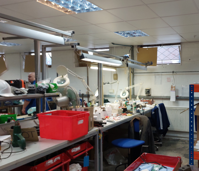
...and an industrial engineering laboratory at my back. Let’s get into the madness, shall we?
The Parts
-
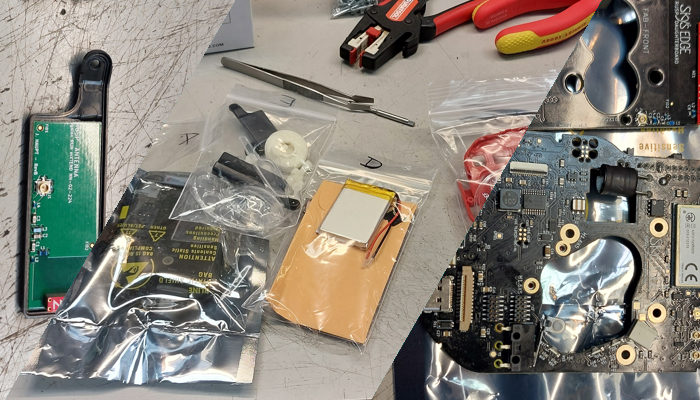
So, after a while when the package of coolness finally arrived, I busted the parts out of their bags and rounded up the usual suspects in the tool-cupboard. Starting us off we've got Bag A. This bag of wonderful things contains a whole host of nuts, washers, screws, and clips, for putting the thing together. Next in the chute we have Bag B, which contains the mechanical parts for the rotary dial mechanism. These are all made of nylon, with some machined metal parts like the governor shaft and the dial shaft. Next is Bag C, which I like to refer to as the Bitch Bag because everything in here is a bitch. Firstly, there's the clock spring, which was hell to install, then there are the magnets, that will stick to any tool you use, and finally there's the mallett spring, which went AWOL somewhere in the chaos AND WE'LL GET TO THAT. After the Bitch Bag we have the I/O bois in Bag D. These are your screens and speaker, and the MicroSD and Battery. There was alos supposed to be a face card in here, but I didn't find it. I don't know if it went missing aswell or if there just wasn't one but that's ok, I like to see what's in things. Finally we have Bag F, the heavy structurals, like the face window, casings, bell, and other assorted goodies. The Motherboard, Daughterboard, Faceboard, and Antenna are bagged separately for static protection and our convenience.
-
Now that we have the gang, we can get cracking with construction. I'm sure nothing will go wrong, for I am a clever and smart girl, who never makes mistakes. Right? Right?! Please, agree with me my self esteem relies on constant validation.
Construction
The Initial Dial Gubbins
-
We can begin by sliding the dial shaft onto the Very Large (tm) gear. Then, we press a bearing into
-
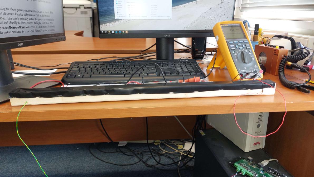
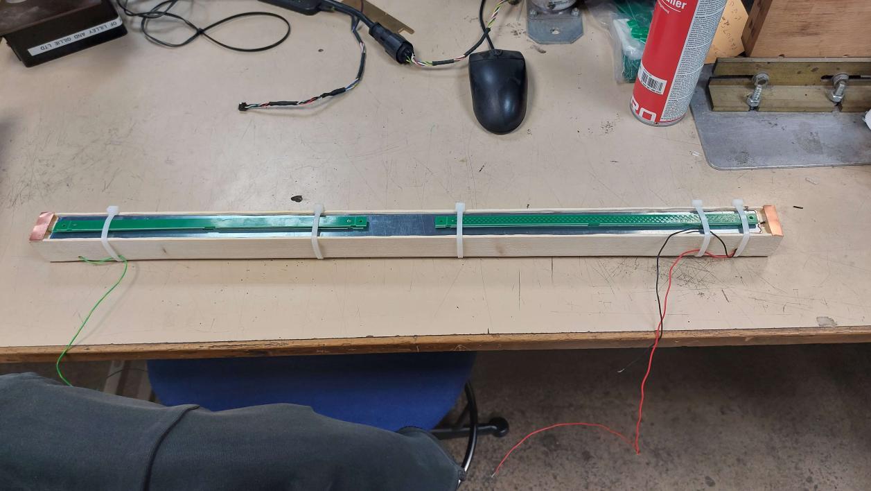
The frame of the ribbon controller also forms the neck of the instrument, which is why it's made of rather sturdy wood. The copper bar wiper is set into the wood in a routed groove, deep enough so when the velostat is stretched over the top there is a gap. This bar then had a single wiore connection soldered to it and was secured in the groove with quick-set epoxy resin. As seen in the picture below, I couldn't get my hands on a clamp, so I got a lot of rip ties, and I used PCB offcuts to distribute the pressdure evenly along the bar. A rip-tie gun was more than enough to get the desired tightness for a mostly even fit. Soldering to the bar was also difficult, as it turns out when you try and solder to it it becomes a massive heat sink. To beat this, we had to head over to the workshop proper and "borrow" Carl's big boy soldering iron. Notice, the two contact bars at each end. These and what forms the connection to the velostat.
-
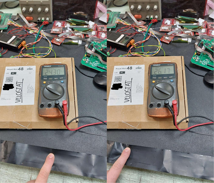
Once the epoxy had dried, we took off the protective coating on the copper and stretched the velostat strip over the wood and the contact bars before securing it in place with double sided tape and staples. Then we began the hell that was testing. Two problems became quite apparent when I began. Firstly, the value would jump all over the place, giving a very unstable reading. Secondly, there was a low-end spike where the value would jump to a high value when you got very close to the connected end. At first I thought this was because of corrosion, but then I realised that it was due to an incomplete surface contact with the velostat connection bars at the ends. This will be solved when the material is clamped down proper with the edging plastic.