The MK1 Modulin
A new fretted way to play a modular synthesizer.
Introduction
-
I want you to know that no matter how bad it is, the original is still an impressive piece of equipment. It's a unique and interesting way to approach playing synth music, and allows you to do some very interesting things with the way you play a monosynth. The format is an interesting concept not only in design but also in performance, as it gives a synth the characteristics of a fretted instrument, freeing the synth player from the keyboard stand allowing him to compete with the lead guitarist on equal footing for his own solo. Before this, you could have a synth solo, but it was always a man standing behind a keyboard, never moving from that spot. With this arrangement, the synth nut can get into the center stage and hog the limelight like any other guitarist or vocalist, making for a much more interesting electronic performace and a projected 25% increase in the likelyhood of (horror of horrors) the keyboardist attracting groupies. The sheer versatility is what captured my imagination when I first saw it. That being said, Martin Wintergatan's Modulin is a piece of garbage. It's made out of stock Doepfer kit that's frankly antequated, it looks like it was knocked together with whatever junk was lying around, and it still has to be connected to a power supply and speaker through this massive cord that comes out the back. Still being hooked up to not only an amp but also a power supply is the opposite of freedom. I think I can do better than that. So, after cruising the usual suspects (MFOS, Instructables, Hackaday), I have come up with for plans for my own system.
-
This one's gonna be the real McCoy. Fully stand-alone, with it's own internal power supply, amplifier, and speaker, with an external output as an option, not as a standard. This is what will make the modulin a truly "take-anywhere" instrument, allowing you to not only beep and boop in your bedroom or garage, but to also board your preferred means of public transport and subject the sunday-morning public to the sound of a VCO being tortured in the name of art. The shops, the streets, the train station, the back of a police car, there is nowhere you cannot inflict your idea of music on the general population. Nobody is safe! NOBODY! MWAHAHAHAHAHAHAHAHAHAHAHAHA!
Design
-
Update when you formalise the designs and stop flying by the seat of your oversized clown pants, you dumbass.
Construction
The Ribbon Controller
-
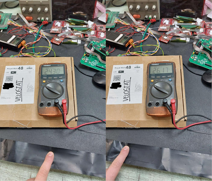
The best place to start was with the thing that I didn't quite know whether it would work or not: a homebrew ribbon controller. The basic Function of the Ribbon is simple: it's a big potentiometer. That's literally
it. The Layer ov velostat behaves like the track with connections at either end, and the copper plate (the zero resistance layer) is like the wiper. When you push the velostat down, it makes contact with the wiper bar below it in a point with a certain resistance. This resistance dictates the note played.
-
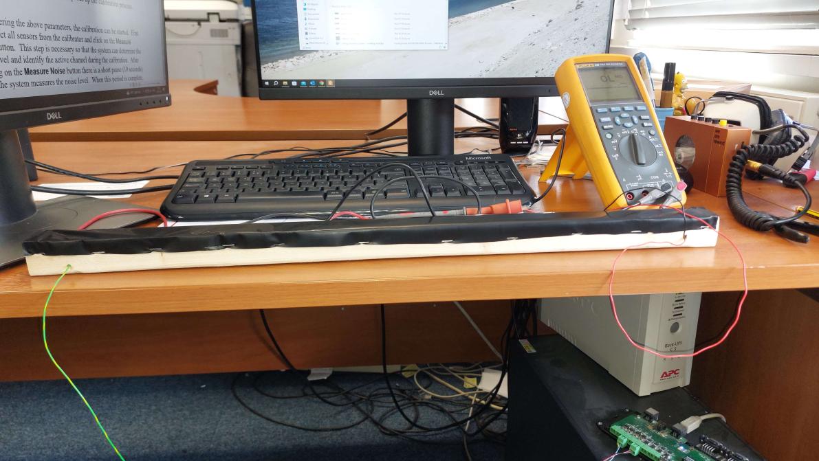
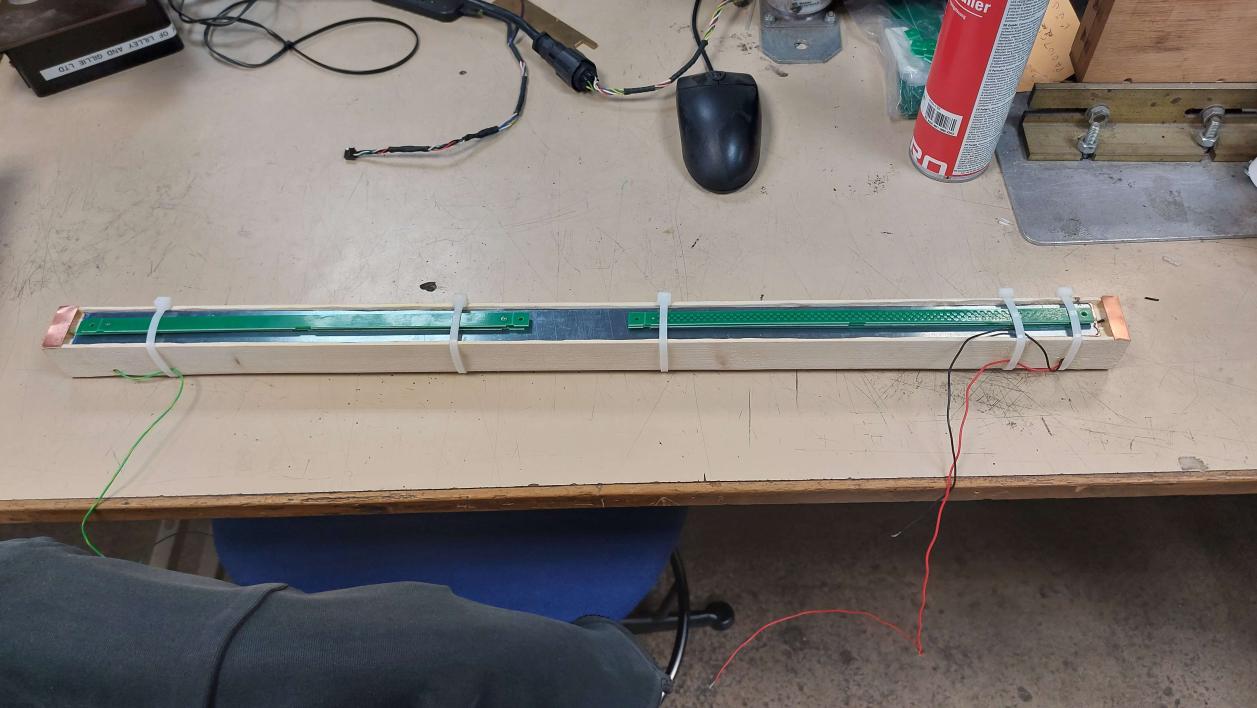
The frame of the ribbon controller also forms the neck of the instrument, which is why it's made of rather sturdy wood. The copper bar wiper is set into the wood in a routed groove, deep enough so when the velostat is stretched over the top there is a gap. This bar then had a single wiore connection soldered to it and was secured in the groove with quick-set epoxy resin. As seen in the picture below, I couldn't get my hands on a clamp, so I got a lot of rip ties, and I used PCB offcuts to distribute the pressdure evenly along the bar. A rip-tie gun was more than enough to get the desired tightness for a mostly even fit. Soldering to the bar was also difficult, as it turns out when you try and solder to it it becomes a massive heat sink. To beat this, we had to head over to the workshop proper and "borrow" Carl's big boy soldering iron. Notice, the two contact bars at each end. These and what forms the connection to the velostat.
-
Once the epoxy had dried, we took off the protective coating on the copper and stretched the velostat strip over the wood and the contact bars before securing it in place with double sided tape and staples. Then we began the hell that was testing. Two problems became quite apparent when I began. Firstly, the value would jump all over the place, giving a very unstable reading. Secondly, there was a low-end spike where the value would jump to a high value when you got very close to the connected end. At first I thought this was because of corrosion, but then I realised that it was due to an incomplete surface contact with the velostat connection bars at the ends. This will be solved when the material is clamped down proper with the edging plastic.